
Surveying the New Optical Form Factors for 400 Gigabit Ethernet
Targeted for massive aggregation of data across an array of applications, 400 Gigabit Ethernet (400GbE) is on schedule for standardization this year within the IEEE 802.3bsTM Ethernet Woring Group. Development of new and faster electrical and optical signaling technologies is simultaneously underway across the ever-expanding Ethernet ecosystem.
Of course, different aspects of the Ethernet ecosystem have different needs in 400GbE I/O form factors. For some, the primary need is density — the goal is to fit as many ports as absolutely possible into a faceplate of 1 rack unit (1RU). For others, the quality of the signal integrity of the given form factor‘s electrical connector might be of greater concern. And how critical is backwards compatibility among the list of priorities? What are the technical and cost implications of offering backwards compatibility? Does the form factor provide sufficient packaging volume? What are the reach requirements?
Plus, as we go to higher data rates, we dissipate more power. With the move to 400-Gbps processing, more components, dissipating more power, are being packed more tightly together within the module and 1RU rack space, making it more challenging to cool the equipment. So, in squeezing I/O ports within the 1RU faceplate to optimize density, is enough open equipment faceplate area being left for perforations for air flow and cooling to maintain system reliability? The answer to that question depends on the thermal-management requirements of the given networking environment.
Each end user, equipment designer, and integrator will have different must-haves and points of emphasis among these and other factors in choosing modules to enable 400GbE networking. Consequently, today‘s different 400GbE module form factors — CFP8, OSFP, QSFP-DD, and COBO — offer different tradeoffs to flexibly satisfy various needs and environments across the exploding Ethernet ecosystem.
With each new data rate, the networking industry often works through multiple pluggable module form factors as technologies mature and networking requirements converge. Once the requirements converge, often the module form factor that best meets all those needs has come to dominate the volumes. For single electrical interfaces (e.g., 10GbE), SFP dominates. For quad electrical interfaces (e.g., 40GbE and 100GbE), QSFP dominates.
Pluggable optical modules in the past have conventionally used single-row connectors mating on the top and bottom of a PCB material card edge interface, with module thermal management based on riding heat sinks and their associated high thermal resistance, etc. However, primary challenges for 400GbE module form factors are that the electrical interface has doubled to eight lanes and thermal management needs to improve, making the existing form factors unacceptable as they are. As we‘ll see below, however, several of the emerging module options build on either SFP or QSFP to meet expected 400GbE requirements.
CFP8
Use of a 16x25G electrical interface provides first-to-market advantage for the CFP8. If 50-Gbps electrical signaling or optical assemblies are not available from the industry in a timely fashion, a 400GbE CFP8 can be achieved using available 25-Gbps components. But this comes at the price of a larger module to house the 16 lanes of electrical and optical elements.
That said, because of this relatively large physical size, CFP8‘s thermal management is good, in that more space means more surface area for heat to spread and air to flow so that thermal loads can be spread around. The tradeoff is that CFP8 — the biggest 400GbE interconnect form factor of them all — offers the lowest port density of the four form factors being considered in this article. The electrical connector used for CFP8 has a single row of contacts on top and bottom in the conventional style.
![]()
Figure 1. A CFP8 form factor optical transceiver.
OSFP
While the OSFP form factor does not provide backwards compatibility to existing form factors, it is designed for maximum thermal and electrical performance.
The "O" is for "octal" — it is being designed to use eight electrical lanes to deliver 400GbE — and "SFP" is for "small form factor pluggable." OSFP is aimed at the upcoming generation of equipment that will operate with 50-Gbps electrical signaling, which is in definition mode right now in the various standards-development projects.
OSFP is a conventional style of electrical interconnect, leveraging best practices that the industry has learned in the past from SFP and QSFP connectors. The electrical connector in OSFP has a single row of contacts on both top and bottom, and it provides robust electrical and signal-integrity performance. Because it‘s faceplate pluggable and field replaceable, it has a single-receptacle electrical connector.
One of the nontraditional aspects of OSFP is that it integrates thermal management (heat sinking) directly into the form factor to help cool the module, similar to the microQSFP form factor that predates it. An OSFP integrated heat sink is intended to enable modules with up to 15 W of power in a switch chassis with conventional front-to-back airflow. This accomplishes two things over a more conventional riding heat sink: It eliminates the high thermal resistance between the module and the heat sink, and, secondarily, once the air exits the back of the module form factor, it is available for cooling the silicon switch or compute chips that are downstream inside the equipment enclosure.
The OSFP receptacle does not offer backwards intermate-ability to existing modules since it favors optimizing the electrical, packaging, and thermal aspects over legacy application support.
![]()
Figure 2. An OSFP form factor optical transceiver.
QSFP-DD
Backwards compatibility is the primary appeal of the QSFP-DD form factor.
The QSFP form factor is today‘s industry workhorse for delivering 40 and 100GbE. The "Q" is for “quad" — a nod to the four-channel electrical interface, with each lane running at 25 Gbps for 100GbE. QSFP-DD adapts the same basic concept as its predecessor, but doubles the electrical contact density, via eight differential pairs capable of 50 Gbps each, to achieve 400GbE, while allowing existing QSFP modules to be plugged into the same cage.
Because it is predicated on delivering the benefit of backwards compatibility, QSFP-DD receptacles and cages need to look like and be configured to receive the existing 40 and 100GbE modules. This is accomplished by extending the length of the QSFP-DD module slightly to add an extra recessed row of contacts on both the top and bottom of the connector. The QSFP-DD specification defines both single-height and stacked configurations of the cage/connector system, each supporting QSFP modules with the original rows of contacts, plus supporting QSFP-DD modules via the additional recessed row of contacts.
The connector‘s recessed row of contacts is an alternative approach for an I/O electrical interconnect, and it demands significant innovation in the area of signal integrity to meet the 50-Gbps channel requirements currently being defined by the IEEE and the Optical Internetworking Forum (OIF). In addition, the baseline requirement to offer backwards compatibility to existing 40 and 100GbE modules means that the mechanical envelope is limited for possible expansion for the new 400GbE optical and electrical subcomponents.
The QSFP-DD MSA has specified two versions. Type 1 is extended in length only enough to accommodate the recessed extra row of contacts for the electrical interface; Type 2 is extended 15 mm further outside of the equipment faceplate for additional packaging volume inside the module.Thermal management is achieved through improvements to cage design, building on the experience of system designs with QSFP; the module can use riding heat sink technology. External non-integrated heat sinks can be incorporated as part of an optimized system design. The specification‘s design is intended to support modules up to at least 12 W. Thermal resistance of a riding heat sink in the past has been at 5 W power levels, and aiming for 10 to 12 W is a significant increase in technical performance.
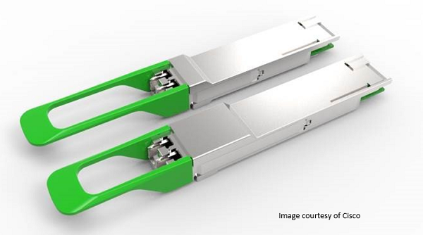
Figure 3. The QSFP-DD Type 1 and Type 2 form factors.
COBO
Embedded optical modules are a key differentiation for COBO, potentially addressing thermal management challenges.
The COBO form factor is named for the Consortium for On-Board Optics, an organization that is defining an interchangeable and interoperable optical module that is installed internally to line-card equipment in a controlled environment by technicians (as opposed to the pluggable modules described above for the other three approaches). The goals are to facilitate higher module port density, improved thermal management, and better power efficiency. This is achieved by mounting the modules around the switch silicon and only putting optical connectors on the faceplate for improved equipment airflow. The COBO form factor holds potential key benefits for the new cloud market model but changes the established equipment-build paradigm.
Because the module is immune to faceplate-density challenges, there is more freedom in defining its footprint. Consequently, COBO is developing both 400-Gbps and 2x400-Gbps capable footprints. Like the OSFP and QSFP-DD form factors, it aims to support an eight-wide electrical interface for 400GbE and is intended to support a similar array of optical interfaces. The high-speed connector that COBO has chosen for this form factor is, like OSFP, a connector with a single row of contacts on top and bottom that can provide the design simplicity needed to achieve good signal integrity performance. A separate low-speed connector is used for the management interface and power contacts. The COBO form factor is intended to support power levels above 15 W.
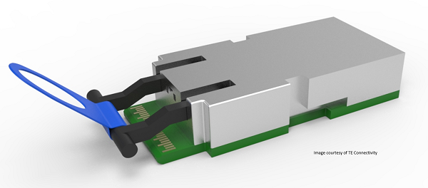
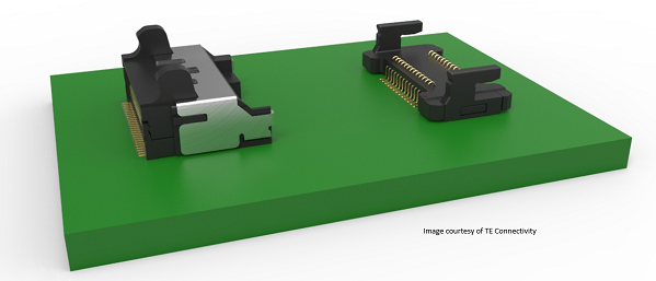
Figure 4. (Top) A COBO form factor (1x400 G Form Factor) transceiver; (bottom) COBO High Speed and Low Speed Connector (1x400G version).
Comparison
The Table and graphic below provide an approximate comparison of the four form factors discussed above.
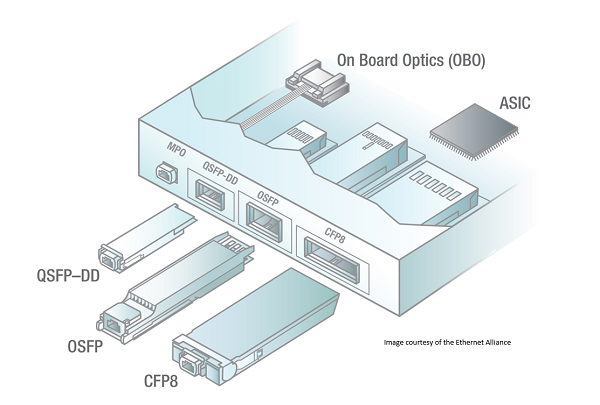
Figure 5. A graphical comparision of the various form factors.
Conclusion
The IEEE P802.3bs standards-development project will define 400GbE transmission for aggregation and high-bandwidth interconnect in key application areas such as cloud-scale data centers, internet exchanges, co-location services, wireless infrastructure, service provider and operator networks, and video-distribution infrastructure. Indeed, with a new era of Ethernet innovation underway, an unprecedented range of standardization efforts is simultaneously underway within the IEEE 802.3 working groups.
As evidenced by creation of four 400GbE form factors — CFP8, OSFP, QSFP-DD, and COBO — equipment manufacturers, system and component vendors, test and measurement providers, and other Ethernet stakeholders are working swiftly to deliver the varied, pay-as-you-grow options that the world will need to satisfy diverse requirements for standardized interface technology. Despite the differences in the form factors we‘ve discussed, it should be noted that all are expected to support industry-standardized electrical and optical interfaces to ensure that systems built with any of them will interoperate in the field.
The Ethernet Alliance will continue to provide insight and education as the industry adoption around these form factors progresses. This will include interoperability testing in Ethernet Alliance-sponsored plugfests.


 ChatNow
 ChatNow
 Mail
Mail